
Power Testing Instruments
GD-500 Automatic Capacitance & Inductance Tester
Bench instrument for measuring high-voltage shunt capacitor banks of reactive power compensation installations and for reactor measurement, without disconnecting the capacitor leads. Uses four-terminal measurement and provides on-board data storage with USB transfer.
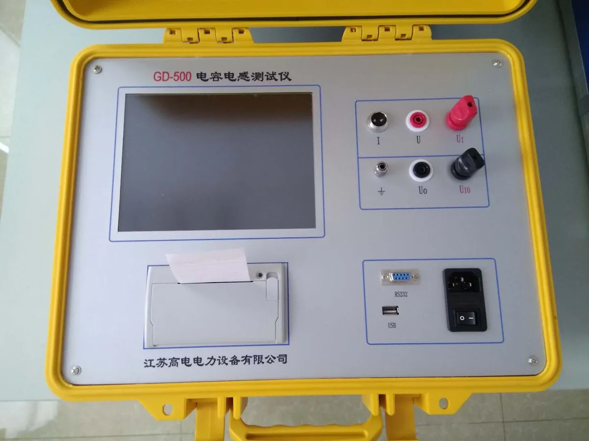
Overview
Bench instrument for measuring high-voltage shunt capacitor banks of reactive power compensation installations and for reactor measurement, without disconnecting the capacitor leads. Uses four-terminal measurement and provides on-board data storage with USB transfer.
Standards & Compliance
Cited in this product’s specification
- SJ-255-10300
Benchmark standards for this equipment category
Systems in this category are commonly specified against these standards, linked to the issuing body. Final configuration and acceptance criteria follow the standard and edition you nominate.
- IEC 60060-1 — High-voltage test techniques
- IEEE 43 — Insulation resistance testing
- IEEE 81 — Grounding resistance measurement
- DL/T 845 — Loop resistance testing
- DL/T 911 — Winding deformation (FRA) test
- JJG 169 — Chinese metrology verification regulation
Application Scenarios
Request Specifications & Quotation
Tell us your test object ratings, the test items you need and the applicable standards. Our sales engineers reply with a configuration proposal and a formal quotation within 24 hours.
Get a QuoteDetailed Description
Overview: the capacitance and inductance tester is used mainly to measure the high-voltage shunt capacitor banks of reactive power compensation installations and to measure reactors. Its measurement basis conforms to the national standard for capacitance measuring instruments, SJ-255-10300. It was developed specifically to address the problems found when measuring high-voltage shunt capacitor banks in the field at substations, and it mainly solves the following problems.
Capacitors can be measured on site without removing the connecting leads, which simplifies the test procedure, improves working efficiency and avoids damage to the power equipment. The complete set of parameters is measured, making it easy to identify changes in capacitor quality and faults in the connecting conductors between components. Large-capacity data storage and USB communication remove the need to transcribe data on site and ensure the integrity of the measured data.
Performance: the instrument uses a superior measurement principle together with four-terminal measurement technology, so measurement is accurate and repeatability is good. It has a large-screen LCD of 320 x 240 dots with Chinese menu prompts, and the LCD has its own touch keys so operation is intuitive and simple. Automatic segmented current compensation linearises the current over the full range and improves measurement accuracy. The waveform and the measured data are displayed at the same time, making the test process more intuitive, and the USB communication function simplifies connection to a PC for transferring and managing measured data.
Equivalent circuit: the instrument calculates the required values from either a series or a parallel equivalent circuit. In the RC internal series or parallel equivalent circuit, Cx is the actual capacitance, Rs is the lead resistance, Lo is the lead inductance, Rp is the inter-electrode insulation resistance and Co is the inter-electrode distributed capacitance. Actual inductors, capacitors and resistors are not ideal reactances or resistances but present themselves as a complex impedance in series or parallel form, so different equivalent circuits give different results, depending on the component concerned. Generally a series equivalent circuit is used for low-impedance components, which are basically high-value capacitances and low-value inductances, whereas a parallel equivalent circuit is used for high-impedance components, which are basically low-value capacitances and high-value inductances. In field use there are only two cases: to test for a change in the internal quality of a device, select the parallel equivalent; to test for a change in the resistance of the external connecting leads, select the series equivalent.
Specifications summary: instrument operating conditions and ratings are an ambient temperature of -10 ℃ to +40 ℃, relative humidity of 90% or less, a working supply of 220 V at power frequency with a tolerance of 10%, a rated frequency of 50 Hz and a rated output of 22 V / 25 A / 500 VA. The instrument measures 360 x 190 x 260 mm (width x height x depth) and weighs approximately 8 kg. The source lists a measuring range, resolution and error section that carries no values.
Technical Specifications
| Measurement basis | Conforms to national standard SJ-255-10300 for capacitance measuring instruments |
|---|---|
| Rated output | 22 V / 25 A / 500 VA |
| Working power supply | 220 V, power frequency, tolerance 10% |
| Rated frequency | 50 Hz |
| Measurement technique | Four-terminal measurement with automatic segmented current compensation |
| Display | Large-screen LCD, 320 x 240 dots, with on-screen touch keys and simultaneous waveform display |
| Data handling | Large-capacity data storage with USB communication |
| Ambient temperature | -10 ℃ to +40 ℃ |
| Relative humidity | 90% or less |
| Dimensions (W x H x D) | 360 x 190 x 260 mm |
| Weight | Approximately 8 kg |
Frequently Asked Questions
What is the GD-500 capacitance and inductance tester used for?
Do the capacitor leads have to be disconnected?
How is measurement data handled?
Further Reading
Method and selection guides that cover the tests this instrument performs.
Reviewed by the Application Engineering Team at Nanjing Gaodian Electric Power Equipment
Specifications are taken from the manufacturer’s technical documentation. Final configuration and acceptance criteria follow the standard and edition you nominate — tell us your test list and we will confirm the ratings.
Related Products
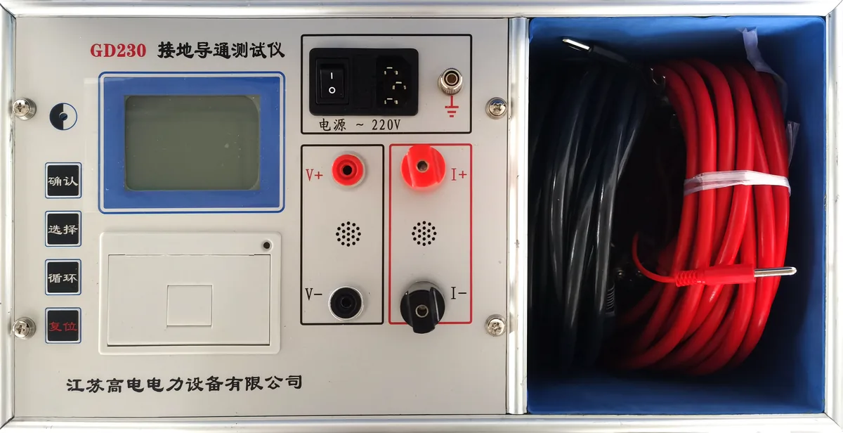
GD230 Ground Continuity Tester
Portable instrument for measuring the continuity resistance between the grounding down conductors of individual items of equipment in a substation. Controlled by a high-performance MCU with automatic current selection, on-board data retention and a thermal printer.
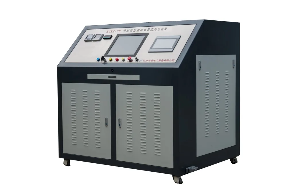
ECBZ-GD Energy-Efficient Transformer Energy-Grade Evaluation System
Automatic evaluation system for the energy-efficiency grade of distribution transformers up to 800 kVA at 10 kV/0.4 kV. Combines intelligent test sequence control, automatic wiring changeover, data processing, data upload and report generation in one bench.
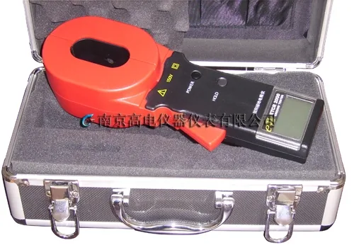
ETCR200 Clamp-on Ground Resistance Tester
Clamp-on ground resistance tester for power, telecom, meteorological and other electrical installations. Measures without auxiliary electrodes, so no disconnection of the grounding conductor and no electrode layout error.
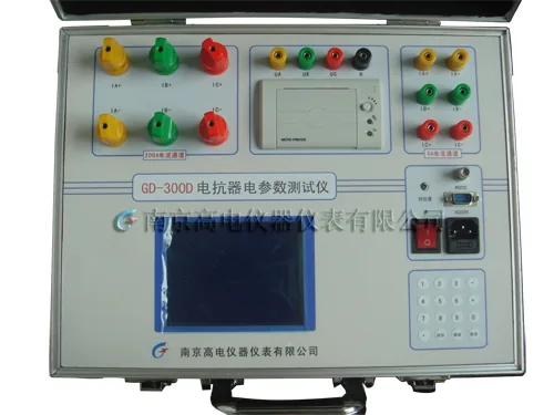
GD-300D Reactor Electrical Parameter Tester (Portable)
Portable instrument dedicated to measuring the electrical parameters of single-phase and three-phase reactors, including AC phase voltage RMS, average voltage, current RMS, active power, reactance and inductance, at 0.5 class accuracy.
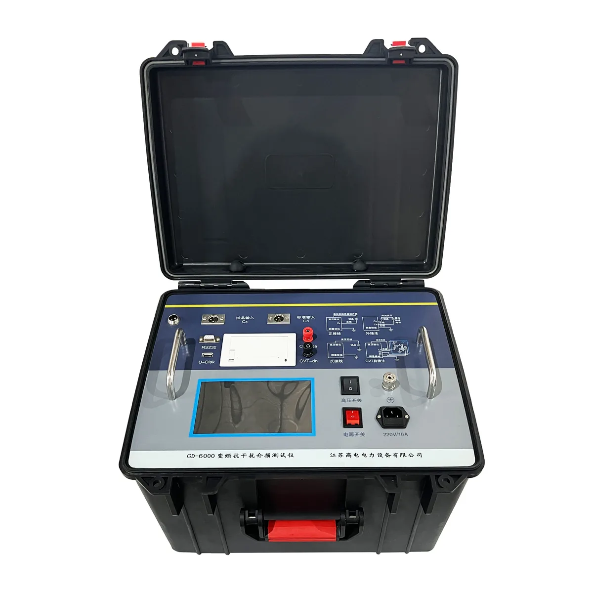
GD6000 Frequency-Shift Dielectric Loss Tester
Fully automatic precision instrument for measuring the dielectric loss tangent and capacitance of high-voltage power equipment at power plants and substations. An internal 45 Hz / 55 Hz source gives accurate results under strong electric-field interference.
GD-300D Reactor Electrical Parameter Tester (Built-in)
Panel-mounted version of the GD-300D reactor electrical parameter tester, using a 320 x 240 dot-matrix LCD with multi-screen menu operation and direct measurement of three-phase reactance, inductance and total active power.
More in Power Testing Instruments
- •GD230 Ground Continuity Tester
- •ETCR200 Clamp-on Ground Resistance Tester
- •GD6000 Frequency-Shift Dielectric Loss Tester
- •GD-210 Large Ground-Grid Resistance Tester (Type CA)
- •GD820 HV Switch Dynamic Characteristic Tester
- •GD240-100A Loop Resistance Tester
- •HV Insulation Resistance Tester (Digital Megohmmeter)
- •Multi-Channel Data Recorder
- •GD6000A Variable Frequency Dielectric Loss (Tan Delta) Tester
- •Insulation Resistance Tester
- •BY2571 Digital Ground Resistance Tester
Need the datasheet for this model?
Send us this product name plus your test requirements. We reply with specifications, photos and a formal quotation.