A transformer winding is a mechanical structure before it is an electrical one. Every through-fault pushes on it with forces proportional to the square of the fault current, every road or rail journey loads it with shock and vibration, and every year of thermal cycling slowly relaxes the clamping pressure that holds the discs and conductors in place. Deformation - axial displacement of discs, radial buckling of the inner winding, tilted conductors, moved leads - is the physical result, and it does not appear in a turns-ratio check, a DC resistance measurement or an insulation resistance reading.
This guide compares the methods that do detect it, explains what frequency response analysis actually measures and what the reference standards define, and sets out the practical conditions that decide whether the comparison against a factory fingerprint is meaningful or a false alarm. It is written for utility test engineers, factory test departments and third-party laboratories assessing a unit after a short circuit, after transport, or during condition assessment.
Why Winding Deformation Matters
Deformation is a mechanical change with electrical consequences. The leakage flux between the windings interacts with the current in the conductors and produces radial and axial forces. The outer winding is pulled outward as hoop stress, the inner winding is pushed inward and tends to buckle, and the axial forces compress the disc stack and, where the clamping pressure is uneven, tilt the conductors and close the oil ducts between them. Short-circuit currents are the dominant cause because the forces scale with the square of the current, but the structure that resists those forces can be weakened long before the fault arrives: pressboard shrinks and the winding compresses with thermal ageing, and the initial clamping pressure relaxes over years of operation. Transport is a second, easily overlooked cause: a unit that passed its routine tests at the works can still be deformed by a road or rail journey if the transport bracing is inadequate. None of these effects is isolated - a winding that has lost clamping pressure has less margin against the next fault, so an event that would be harmless in a new unit can displace turns in an aged one.
- •A deformed winding can pass turns-ratio, DC resistance and insulation resistance measurements, because none of those tests responds to the physical position of the discs and conductors.
- •The effect typically appears later, as local overheating where oil ducts have closed, as partial discharge at displaced conductors, and as dissolved gas in the oil.
- •Short-circuit withstand degrades progressively: a looser winding moves further under the next fault, so the margin keeps falling.
- •After a through-fault the question is not only whether the transformer still works, but whether it still retains its short-circuit withstand margin - which electrical routine tests alone cannot answer.
The Main Detection Methods Compared
| Method | Parameter measured | Sensitivity to deformation | Field or factory | Main standard reference |
|---|---|---|---|---|
| Frequency response analysis (FRA) | Transfer function of the winding, as magnitude and phase against frequency | High - localised axial and radial displacement, buckling, disc displacement, lead movement | Both; a field measurement is compared with the factory fingerprint | DL/T 911 |
| Low-voltage impulse (LVI) | Impulse response of the winding recorded in the time domain and analysed in the frequency domain | High - the same physics as FRA, evaluated from the time-domain record | Both | Same reference-fingerprint principle as FRA |
| Short-circuit impedance / reactance | Short-circuit impedance Zk and its reactive component Xk at a defined tap | Medium to high for gross change; relatively insensitive to a small local displacement | Both; the site measurement needs a stable supply and accurate voltage and current measurement | IEC 60076-5 and GB 1094.5 for the withstand requirement; GB 50150 for the site acceptance test list |
| Capacitance variation | Capacitance between windings and from winding to earth, normally taken with the capacitance and tan-delta measurement | Low to medium; mainly axial displacement and changes at the winding ends | Both; compared against the factory routine test record | Judged against the factory routine test values |
| Ultrasonic or acoustic survey and internal inspection | Structural condition; no electrical parameter | Definitive when an inspection is performed, but there are no published routine acceptance criteria | Mainly factory or workshop, with the unit de-tanked | No standardised routine test; a supplementary method |
| DC resistance and turns ratio | Winding resistance and the ratio between windings | Very low for deformation; effective for turn and disc shorts, and for tap-changer or lead faults | Both; a routine pre-check | IEC 60076-1 |
How Frequency Response Analysis Works
A power transformer winding is not a lumped element. Electrically it behaves as a distributed network of series inductance in each turn and disc, series capacitance between turns and discs, and shunt capacitance from the winding to the core, the tank and the other windings, all with losses. The resonant behaviour of that network - where the resonances fall and how tall the peaks are - is fixed by the physical geometry of the winding. A low-voltage, low-energy signal is applied to one terminal of a winding and the response is recorded at another terminal, with the remaining terminals treated in a defined way. Swept-frequency instruments step a sine wave across a wide band, typically from tens of hertz up to the megahertz region for a power transformer, and record the magnitude and phase of the transfer function; impulse instruments inject a low-voltage impulse and record the response as a time-domain waveform which is then analysed in the frequency domain. Both approaches produce a curve that acts as a fingerprint of the winding geometry. The workflow is comparative. A reference fingerprint is recorded at the factory during routine testing, before dispatch, under stated conditions. Later - at site before energisation, after transport, or after a suspected through-fault - the measurement is repeated and the two curves are compared. Interpretation is band by band: at the low end the response is dominated by the core and the magnetising inductance, in the mid band, where deformation shows most clearly, by the winding distributed inductance and series capacitance, and at the high end by the capacitive network and, importantly, by the test-lead layout. Instrument software can quantify the comparison with correlation coefficients computed over defined frequency bands, which is the mechanism behind the evaluation criteria in DL/T 911. A change in the number or position of the mid-band resonances is the classic sign of mechanical movement; a uniform vertical offset across the whole curve is more often an instrumentation or connection problem than a deformation.
Short-Circuit Impedance, Capacitance and Other Checks
Short-circuit impedance is the classic electrical indicator of winding geometry, because leakage reactance is set by the effective separation and arrangement of the windings. If a winding buckles inward or outward, the leakage path changes and Xk changes with it. The check itself is straightforward: measure short-circuit impedance or reactance on site at a defined tap and compare it with the value from the factory routine test, or with an earlier site measurement at the same tap. IEC 60076-5 and GB 1094.5 use the change in short-circuit reactance measured before and after a short-circuit test as one of the acceptance criteria for the withstand requirement, and GB 50150 lists the site tests for a transformer after installation or after a fault. The practical difficulty is precision rather than principle: at low test currents a small voltage measurement error translates into a significant reactance error, so the instrument and the connection arrangement have to be selected for accuracy, and the tap position and winding temperature have to match the reference conditions. Capacitance variation is the cheapest of the geometric checks. The series capacitance of a winding changes when discs or turns shift, and the winding-to-winding and winding-to-earth capacitances move with axial displacement of the winding ends and with bushing or lead changes. It is normally taken with the capacitance and tan-delta test and judged against the factory record, which makes it useful when no other reference exists but limits its sensitivity to localised deformation. Ultrasonic and acoustic techniques, and direct internal inspection, sit outside the routine electrical test set. Visual inspection after de-tanking is the definitive reference and acoustic survey can suggest a loose winding, but neither has published routine acceptance criteria. DC resistance and turns-ratio measurement are always worth performing, because a disc-to-disc short or a displaced lead will show there; they will not, however, detect a clean mechanical displacement.
Standards, Field Procedure and Interpreting Deviation
- •DL/T 911 defines frequency response analysis for power-transformer winding deformation: the measurement configuration, the comparison against a reference fingerprint, and the criteria for judging the result.
- •IEC 60076-5 and GB 1094.5 define the requirement for a transformer to withstand a short circuit and treat the change in short-circuit reactance as one of the acceptance criteria; that is the reference against which an impedance comparison is made.
- •GB 50150 sets out the site acceptance tests for electrical installations, including the transformer tests performed after installation and after a suspected fault, and IEC 60076-1 covers routine transformer measurements such as ratio and winding resistance.
- •Lock the tap position before the test and record it. Tap position is the single most common cause of a false deformation alarm, because it changes the winding geometry being measured.
- •Ground the tank and the core, route the test leads in exactly the same way as during the reference measurement, and keep them clear of earthed steelwork. The high-frequency part of the curve responds to the lead layout as much as to the winding.
- •Do not run the measurement immediately after a DC resistance test. DC current leaves the core magnetised, which distorts the low-frequency part of the response; demagnetise or allow the core to settle, and always take a repeat measurement to confirm repeatability first.
- •Record the winding temperature and the tap position with every measurement. Deviation spread evenly across the whole curve is usually a measurement problem; a localised change in the mid-frequency resonances is what a real deformation looks like.
- •When a deviation is found, escalate in order of cost: repeat the measurement under controlled conditions, then compare it with the short-circuit impedance and capacitance records, then consider internal inspection. The standards give band-wise criteria - they are not a single pass or fail number.
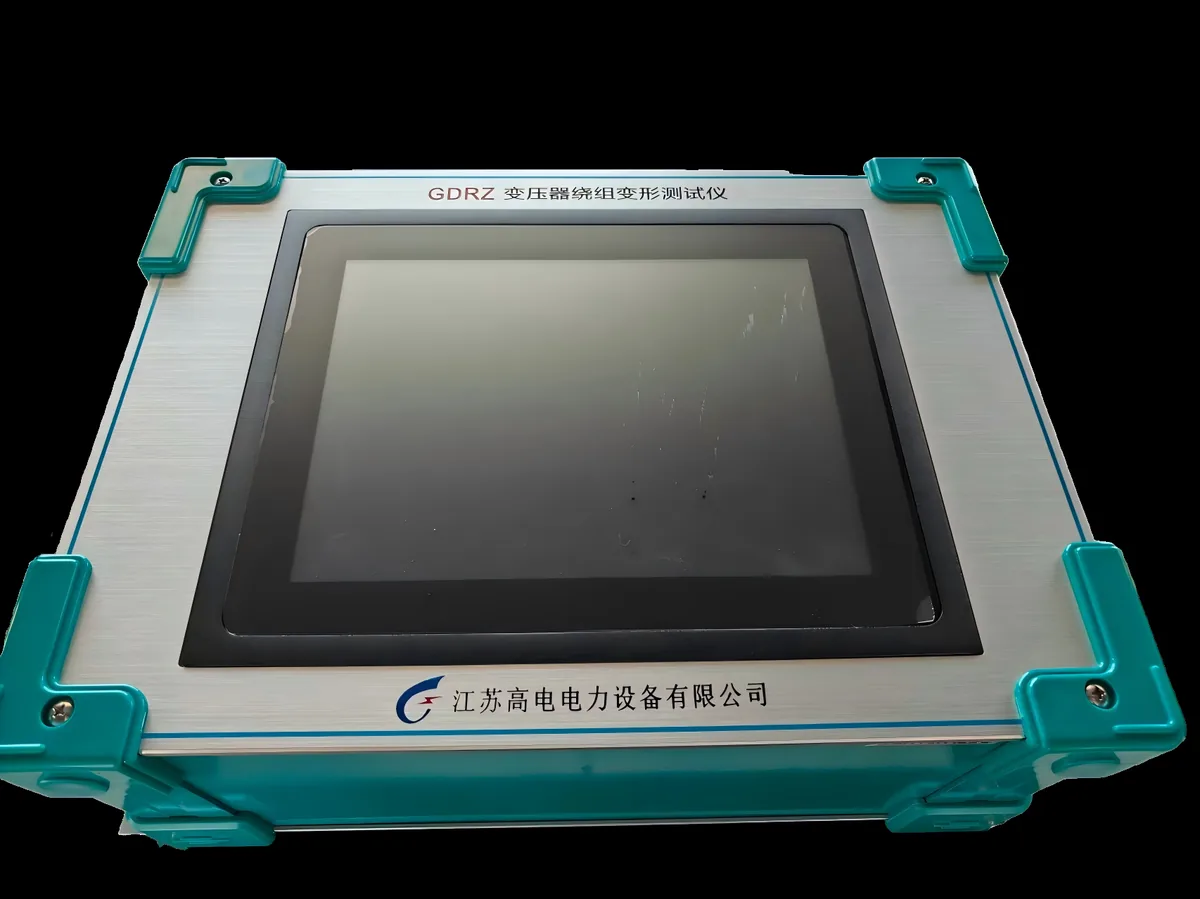
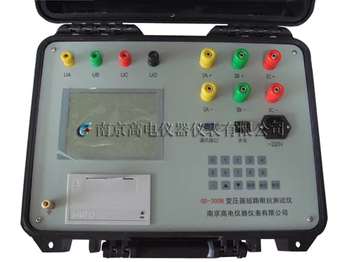
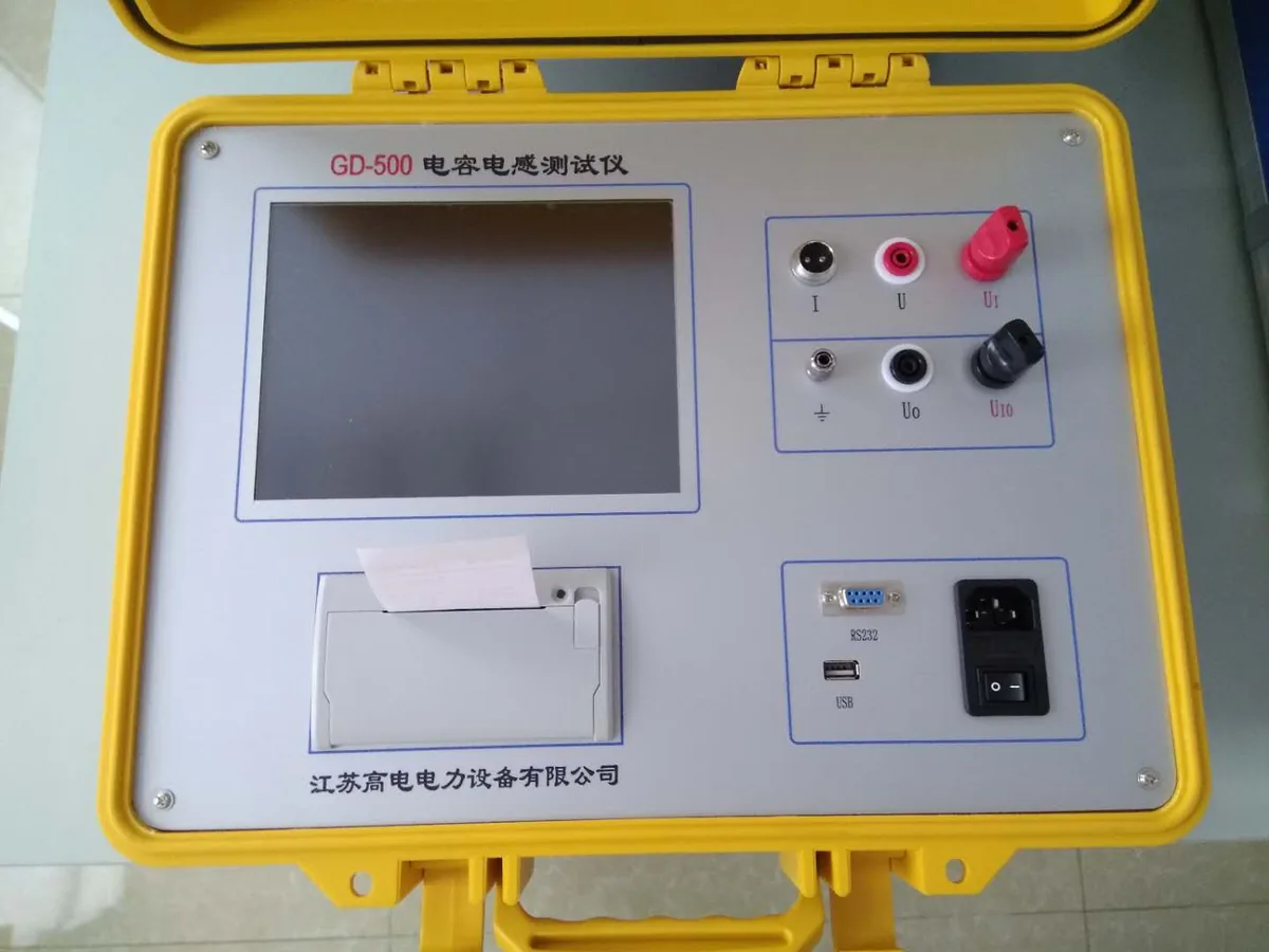
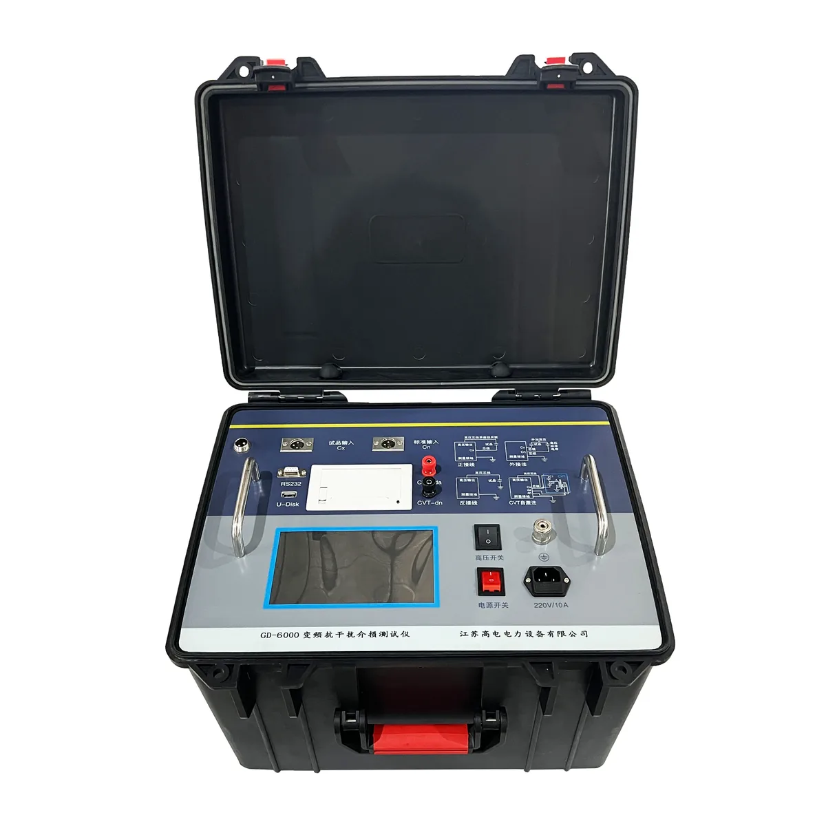
Winding deformation testing is a comparison discipline rather than a single instrument reading, and the value of the result depends almost entirely on the quality of the reference. The foundation is a well-recorded baseline: a factory fingerprint for FRA, a factory short-circuit impedance and capacitance record, and a site measurement taken before first energisation. With those in place, an FRA comparison and a short-circuit impedance comparison answer most post-fault and post-transport questions without de-tanking the unit. A GDRZ winding deformation tester follows the FRA and low-voltage impulse method and a GD-300B measures short-circuit impedance on site; either instrument can be configured to the standard and the evaluation criteria your specification calls for.
Reviewed by the Application Engineering Team at Gaodian Electric Power Co., Ltd
Gaodian Electric Power Co., Ltd designs and manufactures high-voltage test systems for transformer factories, power utilities and third-party laboratories. This guide is a selection reference, not a compliance statement: final equipment configuration and acceptance criteria follow the standard and edition you nominate.