An HV test laboratory is usually specified in the wrong order: the equipment list is written first, the building is found afterwards, and then someone discovers that the shielded room does not fit through the door or that the crane cannot place the test transformer on its plinth. The cost of that order is real, because the building, the earthing and the safety interlocks are the items that cannot be changed after commissioning.
This checklist works from scope to section order. It describes the equipment layers that make up a test hall, compares the three tiers of laboratory seen in practice — incoming-inspection, factory outgoing-test line, and third-party or research laboratory — and lists the layout, service and calibration items that decide whether the hall can be operated as designed. The method benchmarks referred to throughout are IEC 60060-1, IEC 60270, GB 50150 and GB/T 16927.1.
The equipment layers of an HV test hall
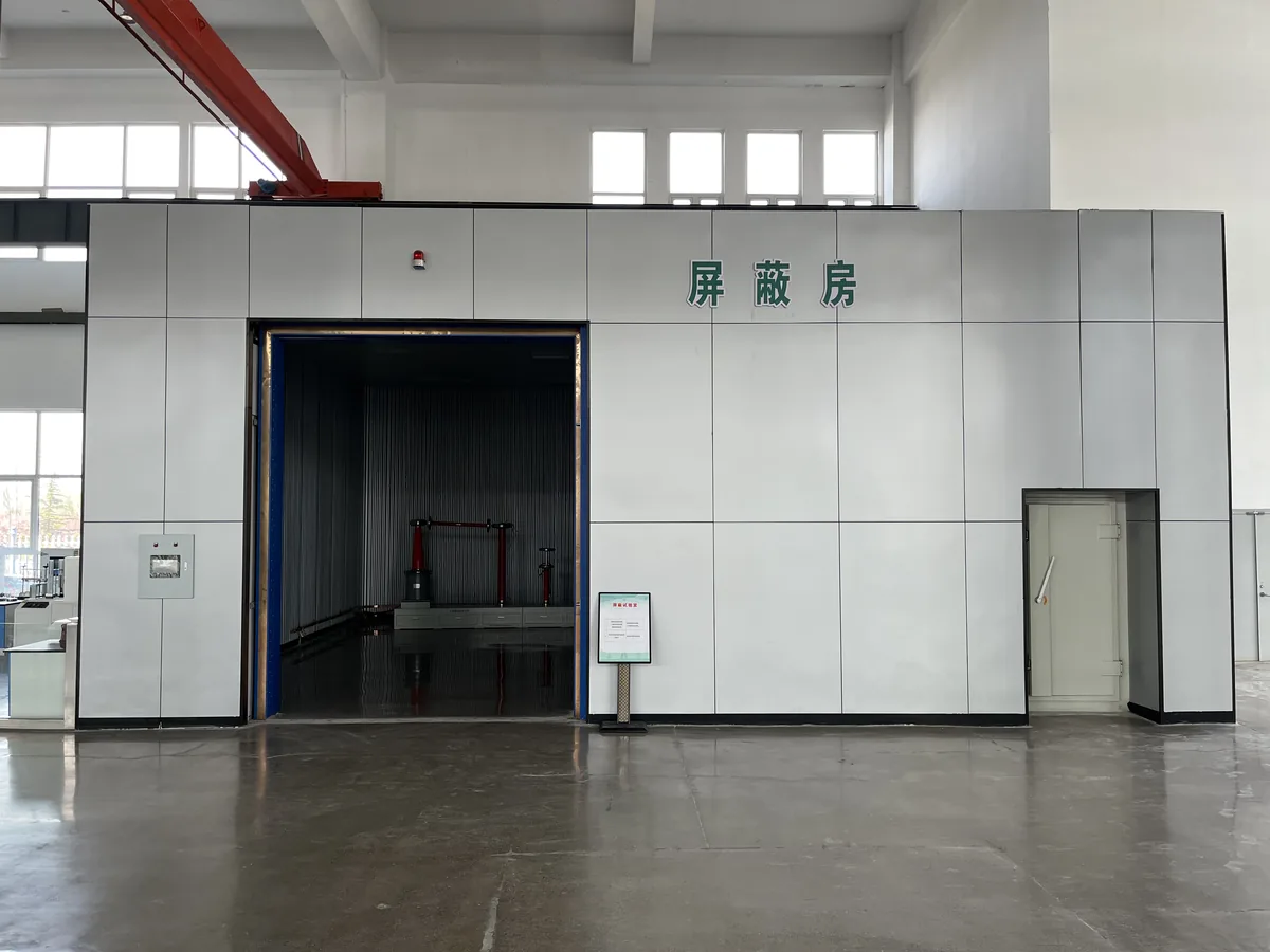
A test hall decomposes into layers: power supply and regulation; test-voltage generation; measurement; partial-discharge detection; the building services that make those layers usable, including shielding, the control room and the artificial rain test room; earthing and safety interlocks; and data recording. The layers are not independent. The partial-discharge background level a laboratory can demonstrate depends on the quality of the supply and of the shielding together, the uncertainty of a dielectric test depends on the reference capacitor and the divider, and an impulse waveform depends on the generator and on the load it sees. That is why the specification should be written from the measurement layer outwards: decide the measurement uncertainty and the discharge level you must resolve, and the requirements for everything upstream follow from it. Writing the equipment list before that decision is what produces a hall that passes its first acceptance test and then cannot demonstrate the background level the standard requires.
Power supply, regulation and filtering
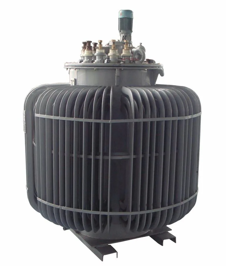
The supply and regulation layer sets the quality of everything downstream. For AC withstand tests the voltage is regulated, commonly by an induction voltage regulator or by a variable-frequency source, and the supply is taken through an isolation filter and transformer to attenuate harmonics and conducted noise arriving from the mains. For partial-discharge measurement the same layer is what keeps the background low enough to resolve the discharge magnitudes the standard is concerned with: a shielded room reduces interference from outside, but shielding cannot clean a noisy supply. The ratings follow from three numbers — the highest test voltage, the capacitance of the load, and the current the test object draws. For inductive voltage transformers the last one matters because the magnetising current rises with the frequency used in induced-voltage tests, and for cable or GIS loads it is the load capacitance that decides the required source current. Where three-phase induced-voltage or three-phase withstand tests are part of the scope, a three-phase regulator and filter belong in this layer from the start rather than being added afterwards.
Measurement, partial discharge and data
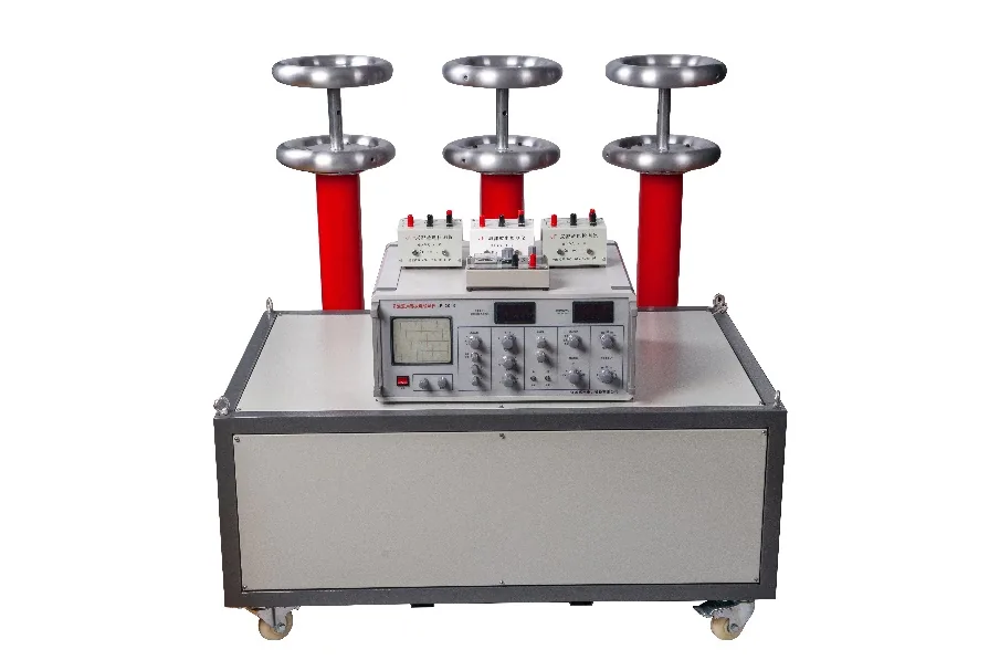
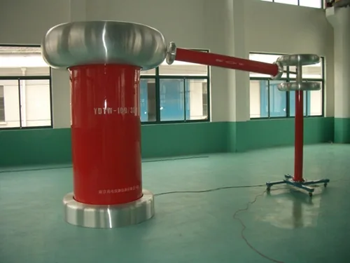
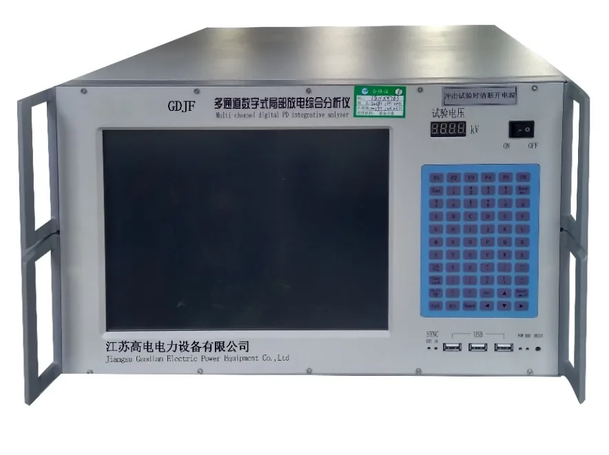
Measurement is a chain — reference, connection, coupling unit, recording instrument — not a single box. IEC 60060-1 and GB/T 16927.1 define how a test voltage is measured and corrected for atmospheric conditions; IEC 60060-2 defines how the measuring system itself is validated; IEC 60270 defines the partial-discharge quantity, its calibration and its measurement. Three practical consequences follow. First, a standard capacitor and a divider each need their own documented scale factor and their own calibration record. Second, partial-discharge calibration should be performed by injecting a calibrator at the test object, not assumed from a stored figure, and the background level should be measured and recorded under the conditions in which tests will actually run. Third, the data layer — a multi-channel recorder or a bench controller — should timestamp and store the raw waveform, so that a result can be re-examined later against the procedure that produced it. Where the load is capacitive and the current requirement high, series resonant sets deliver the test voltage from a considerably smaller supply than a conventional transformer-based set, which changes both the electrical layout and the space needed for it.
Three lab tiers and what belongs in each
| Lab tier | Typical work | Core equipment | Method benchmarks |
|---|---|---|---|
| Incoming-inspection laboratory | Routine checks on switchgear, instrument transformers, cables and small transformers delivered to a site or a works | AC withstand set, insulation-resistance and resistance testers, turns-ratio and loop-resistance instruments, dielectric-loss or capacitance instrumentation, mobile test vehicle for on-site work | IEC 60060-1; GB/T 16927.1; GB 50150 |
| Transformer factory outgoing-test line | Routine and type tests on new transformers before dispatch | Induction voltage regulator, isolation filter, PD-free AC test transformer, standard capacitor and dividers, partial-discharge measurement system, impulse generator where impulse tests are in scope, test bench with data recording, shielded enclosure for discharge measurement | IEC 60076-1; IEC 60076-3; IEC 60270; GB 1094.1; GB 1094.3 |
| Third-party or research laboratory | Witnessed acceptance and type testing, failure investigation, calibration support across several equipment classes | All of the factory layer, plus series resonant sets for high-capacitance loads, impulse generators with full waveform measurement, artificial rain test room, central control room, shielded room with verified background level, environmental correction instrumentation | IEC 60060-1; IEC 60060-2; IEC 60270; GB/T 16927.1 |
Scope, layout and the order of work
- •Decide the highest voltage class first. A hall rated for 35 kV apparatus and one rated for 220 kV or 500 kV substation equipment differ in working clearances, in the test transformer, in the impulse generator and in the building itself.
- •Fix the test objects and their ratings: the largest transformer, the highest-capacitance cable or GIS section you intend to test, and the heaviest single item that must be moved into the hall and placed on a plinth.
- •Write the test list with the standard behind each item — applied withstand, induced withstand, lightning impulse, partial discharge, temperature rise, ratio and polarity, winding resistance, frequency-response baseline — because each item adds an equipment layer and sometimes a building requirement.
- •Set the throughput. How many units per shift, and which tests can run in parallel, decides the number of test bays, the control-room layout, and whether one voltage source is enough.
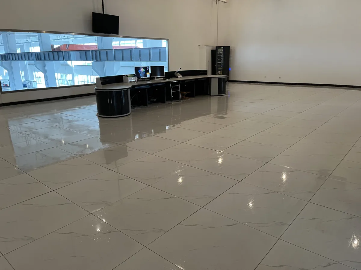
- •Confirm clearances and access before drawing the layout: the working distance implied by the test voltage, the door opening and crane capacity for the largest object, the turning space for a mobile test vehicle, and the separation between the high-voltage area and any occupied desk space.
- •Treat the shielded enclosure as a building item rather than a purchase. It needs its own floor slab and its own earthing arrangement, and the ring main or bus connection into the hall should be drawn before the slab is poured.
- •Plan the services early: drainage for the artificial rain test room, ventilation for the impulse generator area and any oil handling, and lighting arranged so that it does not create a discharge path or an optical path to the PD detector.
- •1. Write the scope document: voltage class, largest test object, test list, throughput, and the standard each test answers to.
- •2. Choose the measurement layer first — divider, reference capacitor, required uncertainty, discharge level to be resolved — then work upstream to the source.
- •3. Select the voltage sources: AC test transformer or series resonant set, plus an impulse generator if impulse tests are in scope, together with the regulation and filtering they require.
- •4. Specify the partial-discharge system and the shielding as one decision, and state the background level the laboratory is expected to demonstrate.
- •5. Fix the building items: slab and earthing for the shielded enclosure, clearances, control-room position, rain-room drainage and ventilation.
- •6. Design the safety layer: earthing and discharge devices, interlocks on gates and doors, emergency trip, warning devices and access control.
- •7. Specify the data layer: what is recorded, at what resolution, in what format, and how each record is linked to the serial number of the object tested.
- •8. Commission in a fixed sequence — earthing verification and interlock proving, then source and regulation, then measurement validation, then background measurement, then a dry run on a known test object.
- •9. Calibrate and document: reference calibration for dividers and standard capacitors, verification of the discharge calibrator, and a written verification interval for every instrument in the chain.
If you take one rule from this checklist, take the order: scope, then measurement, then source, then building, then safety and data. Most problems that surface after commissioning — a discharge background higher than planned, a hall that cannot accept the largest transformer, a measuring chain with no documented scale factor — trace back to a decision taken out of sequence. Put the standards and the acceptance limits into the scope document before the first purchase order, and re-issue that document after commissioning with the measured background level and the calibration records attached, so the laboratory can be shown to do what it was built to do.
Reviewed by the Application Engineering Team at Gaodian Electric Power Co., Ltd
Gaodian Electric Power Co., Ltd designs and manufactures high-voltage test systems for transformer factories, power utilities and third-party laboratories. This guide is a selection reference, not a compliance statement: final equipment configuration and acceptance criteria follow the standard and edition you nominate.