Insulation resistance is the oldest measurement in the electrical test report and the one most often misread. The number itself, megohms at one minute, depends on the insulation temperature, the humidity, the surface condition of the bushings, the test voltage and the instrument, so a single reading compared against a table copied from another site proves very little. What carries information is the shape of the charging curve and the trend over time at the same temperature.
This guide sets out the test voltages used for each voltage class, how the polarisation index and dielectric absorption ratio are defined and read, what step-voltage and ramp tests add, and a field checklist covering preparation and safety as well as the measurement.
What Insulation Resistance and Absorption Measurements Tell You
Insulation resistance is a DC measurement of the leakage path through and over the insulation, taken at a defined test voltage and read at defined times. When the test voltage is applied, three currents flow: a capacitive charging current that decays within seconds, an absorption or polarisation current that decays slowly as charge redistributes inside the dielectric, and a steady leakage current governed by conduction through the material and over its surface. The instrument reads the sum, so the value falls during the first minute and stabilises as the capacitive and polarisation components die away. The steady part of the reading is a bulk indicator: moisture, carbonisation, contamination and gross cracking all create conduction paths and push the value down. The decay behaviour is a second and independent indicator - dry, sound insulation polarises slowly and the resistance keeps climbing, while wet or degraded insulation polarises less and the reading settles early. That is the whole basis of the PI and DAR ratios.
| Measurement | What it detects | Typical interpretation | Caution |
|---|---|---|---|
| IR at one minute, at the selected DC test voltage | Conductive leakage paths: moisture, contamination, carbonisation, gross cracking | A high and stable value is the expected result; the acceptance value depends on the equipment class and the applicable standard | A reading dominated by surface leakage can substantially understate the true condition of the insulation |
| Dielectric absorption ratio, DAR = IR(60 s) / IR(15 s) | The early, fast part of the charging curve; a quick first indication of moisture | A rule of thumb is that a value above roughly 1.25 to 1.4 is normally treated as healthy; a value near 1.0 suggests little polarisation, often from moisture or contamination | Not meaningful when the reading is above the instrument range, or when the specimen capacitance is very small |
| Polarisation index, PI = IR(10 min) / IR(60 s) | The slow polarisation behaviour; far less temperature-dependent than the absolute value | Commonly used guide: about 2.0 and above is treated as satisfactory, roughly 1.0 to 2.0 warrants investigation, and below 1.0 is unusual | Requires a stable instrument over the full ten minutes; a temperature change during the test invalidates the result |
| Step-voltage test | Whether the resistance holds up as the applied DC voltage increases | Insulation that is sound holds or increases; a flat or falling trend suggests moisture or a localised defect | The final step must stay within the test voltage appropriate to the equipment class |
| Ramp test | Whether the leakage current stays proportional as the voltage rises continuously | A current that rises disproportionately or becomes unstable points to insulation weakness | Needs a test set with a continuously variable output and live current monitoring |
| Guarded measurement | Surface leakage current, separated from the volume resistance | A large difference between guarded and unguarded readings indicates surface contamination rather than a defect in the insulation itself | The guard connection is made to the insulation surface, never to the winding |
- •Insulation resistance is a bulk, low-sensitivity measurement: it can show that insulation is wet or contaminated, but it cannot locate a defect or replace a tan-delta or partial-discharge test.
- •A high reading does not prove sound insulation, because a localised void or a small delamination leaves the bulk resistance largely unaffected.
- •Surface leakage over dirty or damp bushings can dominate the result and hide the condition of the insulation behind it, which is exactly the case the guard terminal exists for.
- •The value depends strongly on temperature, so a reading is only comparable with another reading taken at the same temperature.
Choosing the Test Voltage
The test voltage is chosen so that the insulation is stressed enough to reveal conduction paths, but not beyond what the equipment is designed to withstand. As a rule of thumb the DC test voltage steps up with the rated voltage class: 500 V for low-voltage control and secondary circuits, 1 kV for low-voltage power equipment and auxiliary circuits, 2.5 kV for medium-voltage switchgear, cables and small machines, 5 kV for high-voltage transformers, bushings, cables and motors, and 10 kV for extra-high-voltage apparatus and large power transformers. Where a standard or the manufacturer specifies a test voltage for a particular equipment class, that value governs. Two principles sit behind the numbers. First, the voltage must be high enough that the steady leakage current is measurable above the instrument noise floor; at too low a voltage the reading is dominated by surface leakage. Second, it must stay well inside the design stress of the insulation, because insulation resistance testing is a diagnostic rather than a proof test; the dielectric withstand check is a separate test carried out at power frequency. The relationship between test voltage and winding rated voltage for rotating machines is discussed in IEEE 43, and DL/T 596 sets out the test voltages and acceptance values applied to power equipment in the Chinese system.
Polarisation Index and Dielectric Absorption Ratio
The two ratios come from the same measurement, taken at different elapsed times. The dielectric absorption ratio is the one-minute value divided by the fifteen-second value, DAR = IR(60 s) / IR(15 s); it captures the early, fast part of the absorption curve and is quick to obtain. The polarisation index is the ten-minute value divided by the one-minute value, PI = IR(10 min) / IR(60 s); it uses the slow part of the curve and is therefore much less sensitive to temperature than the absolute reading. As a rule of thumb, a DAR above roughly 1.25 to 1.4 and a PI above about 2.0 are treated as healthy for common insulation systems, while a PI between 1.0 and 2.0 is treated as questionable and calls for investigation rather than immediate condemnation. A ratio close to 1.0 means the insulation is barely polarising, which is typical of wet or heavily contaminated insulation but also occurs where the insulation simply contains little absorbent material. The published criteria differ between equipment classes, and the values applied to rotating machines for a polarisation index are not automatically transferable to oil-immersed transformer insulation; where a site standard exists, DL/T 596 provides the values used for power equipment. Two conditions decide whether the ratio is valid: the insulation temperature must be steady throughout the ten minutes, and the instrument must hold a stable output for the whole period.
Step-Voltage, Ramp Tests and Temperature Correction
The step-voltage test checks how the insulation behaves as the applied voltage changes. Resistance is measured at equal time intervals at successive voltage steps, commonly five steps from one fifth to the full test voltage, and the values are plotted against the applied voltage. Sound insulation shows a resistance that holds or rises as the voltage increases, while insulation with moisture or a localised defect tends to flatten or fall, because conduction becomes non-linear as the stress rises. The ramp test applies a continuously rising voltage up to the specified maximum while the current is monitored, and it is used mainly on rotating-machine insulation, where IEEE 43 discusses the method; a current that rises disproportionately or becomes unstable points to insulation weakness. Temperature correction matters because resistance falls steeply as the insulation warms. The widely used rule of thumb is that the value halves for roughly every 10 degrees Celsius of temperature rise, which is why an uncorrected comparison between a cold morning reading and a hot afternoon reading can look like a fifty per cent deterioration when nothing has changed. Correction curves are specific to the insulation system and come from the standard or the instrument documentation. The polarisation index is comparatively insensitive to temperature, which is one reason it is preferred over the bare one-minute value, while DAR is more affected. Whatever the method, every reading must be recorded with the insulation temperature and the ambient conditions at the time of test.
Safety, Preparation and the Field Checklist
- •Isolate the equipment, prove dead, and confirm the absence of voltage with a calibrated detector before any test lead is connected.
- •Disconnect external connections that would distort the measurement, including surge arresters, instrument-transformer secondaries and any neutral or earthing links the test configuration requires to be opened.
- •Choose the test voltage from the equipment voltage class and any standard or manufacturer instruction, and record the value used.
- •Check the instrument and the leads before the test: a self-test and a lead short-circuit check catch most of the errors that later appear as impossible readings.
- •Clean and dry the bushings, and fit the guard connection to the insulation surface where humidity or contamination could create a surface leakage path.
- •Record the insulation temperature, the ambient temperature and the humidity before the voltage is applied.
- •Apply the test voltage, note the 15 second and 60 second values, and run to ten minutes where a polarisation index is required, taking each reading when the display is stable.
- •Run the step-voltage test, or the ramp test, where the standard or the condition assessment calls for it.
- •Record every value with the temperature, the test voltage, the instrument and the lead and guard configuration, then compare it with the previous trend and the factory value rather than with an absolute threshold.
- •Discharge the winding to earth and confirm the discharge path; a capacitive specimen stores a dangerous charge, so keep it earthed for at least the duration of the test before anyone touches it, and restore the connections and the work permit only afterwards.
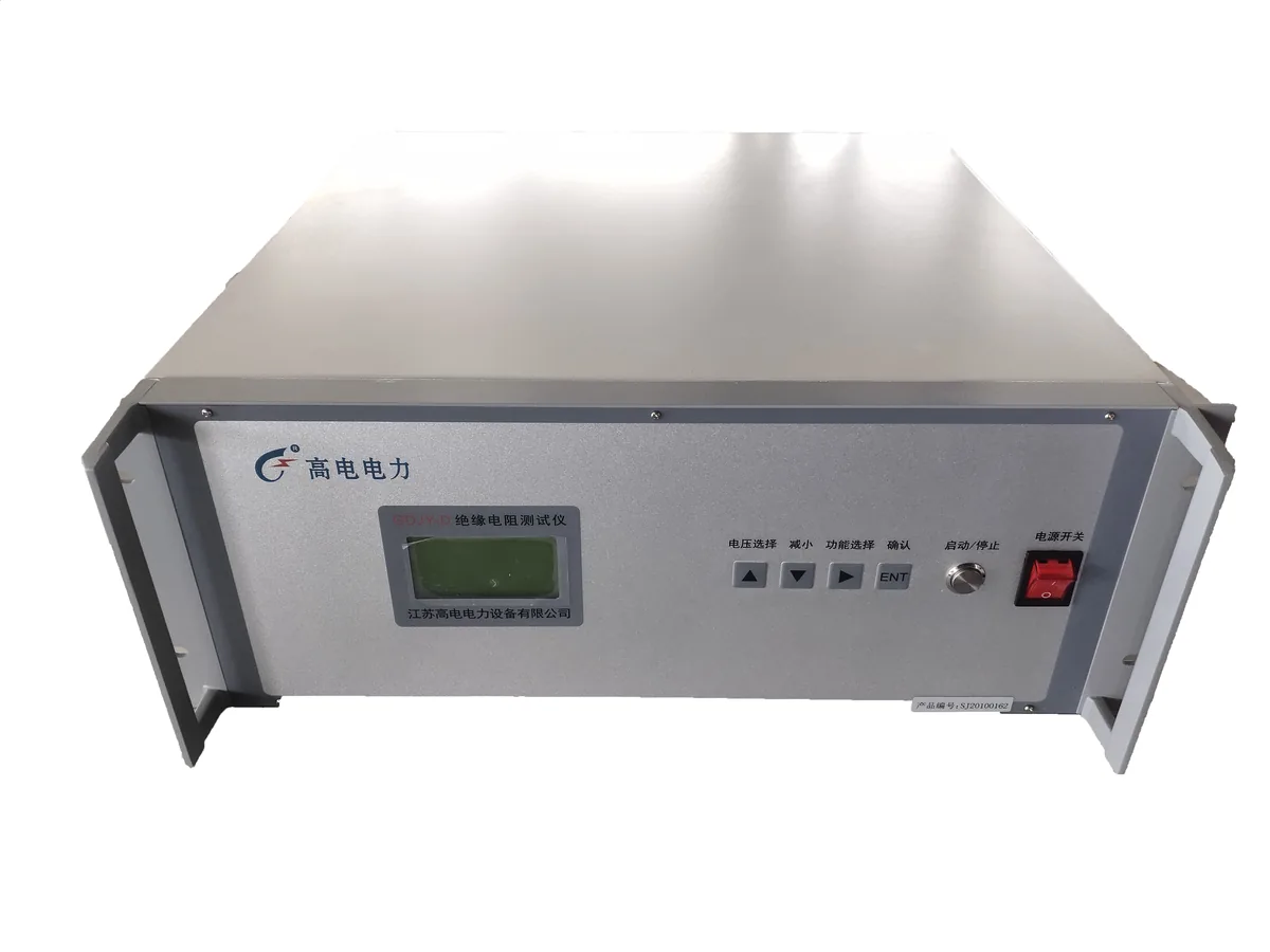
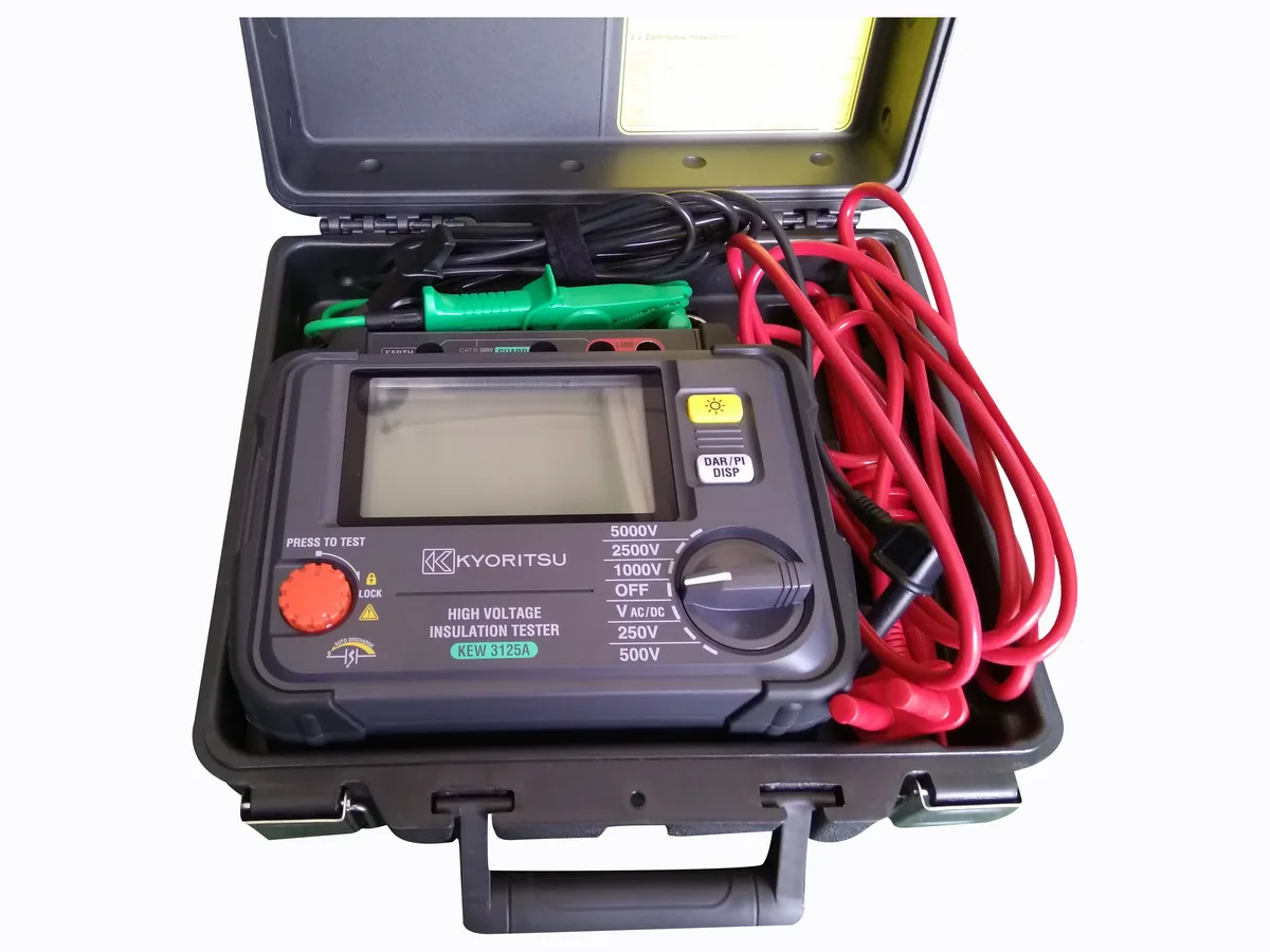
Insulation resistance testing earns its place in a condition-assessment programme when the readings are comparable: the same test voltage, the same lead and guard arrangement, the temperature recorded, and the same time points every time. Under those conditions the trend line is the measurement, and the polarisation index and absorption ratio add a second dimension at no extra cost. Our insulation resistance testers cover the test voltages discussed here and can be configured to the voltage and evaluation criteria your standard specifies; the ratio criteria themselves always come from the standard you are working to.
Reviewed by the Application Engineering Team at Gaodian Electric Power Co., Ltd
Gaodian Electric Power Co., Ltd designs and manufactures high-voltage test systems for transformer factories, power utilities and third-party laboratories. This guide is a selection reference, not a compliance statement: final equipment configuration and acceptance criteria follow the standard and edition you nominate.