
High Voltage Test Equipment
Three-Phase Induction Voltage Regulator
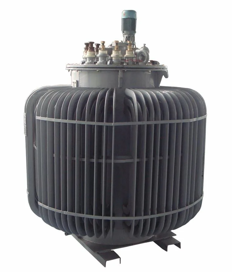
Vertically mounted induction voltage regulator built like a wound-rotor motor, with electric and manual worm-gear drive, raise and lower direction indicators, limit switches and a stopper. Input and output terminals are brought out to a terminal board in the junction box.
Overview
Vertically mounted induction voltage regulator built like a wound-rotor motor, with electric and manual worm-gear drive, raise and lower direction indicators, limit switches and a stopper. Input and output terminals are brought out to a terminal board in the junction box.
Standards & Compliance
Benchmark standards for this equipment category
Systems in this category are commonly specified against these standards, linked to the issuing body. Final configuration and acceptance criteria follow the standard and edition you nominate.
- IEC 60060-1 — High-voltage test techniques - General definitions and test requirements
- IEC 60060-2 — High-voltage test techniques - Measuring systems
- IEC 60270 — Partial discharge measurements
- GB/T 16927.1 — High-voltage test techniques
- GB 7354 — Partial discharge measurement
Application Scenarios
Request Specifications & Quotation
Tell us your test object ratings, the test items you need and the applicable standards. Our sales engineers reply with a configuration proposal and a formal quotation within 24 hours.
Get a QuoteDetailed Description
Scope of application and working conditions: the operating environment of the regulator must be at an altitude no higher than 1000 m, with an ambient medium temperature no greater than +40 ℃ and a relative air humidity no greater than 85%. The regulator is used in an environment free of chemically corrosive gases and vapours, in an atmosphere without explosive hazardous gases, and in a location not exposed to rain ingress.
In general, unless a current-limiting device is added, two or more units cannot be used in parallel.
Structural features: the regulator structure divides into two parts, the main body and the transmission control.
The main body is like a wound-rotor asynchronous motor, consisting of a stator, a wound rotor and two end covers, front and rear, and it is installed vertically. Regulator windings are generally a double-layer short-pitch lap winding for three-phase units and a single-layer concentric winding for single-phase units.
The transmission control is dual-purpose, electric and manual, and is clearly marked with raise-voltage and lower-voltage direction indicator plates. The electric and manual transmission consists of two pairs of worm gears and worms, a handwheel, a drive motor, a limit switch and a stopper. The first pair of worm gear and worm is assembled with the drive motor to reduce the motor speed and drive the second pair. In normal service the servo motor on the regulator is controlled to run forwards or backwards from the buttons of the remote control device, changing the regulator output voltage. The handwheel drive is normally used for fine voltage adjustment, and also ensures that the regulator can still be adjusted normally if the drive motor fails. The limit switch cuts off the motor supply automatically when the regulator output voltage reaches its upper or lower limit, while the stopper restricts the rotor to rotation within the specified mechanical angle.
Wiring: the input and output connections of the regulator are all made on the terminal board inside the junction box on the machine body. Input terminals are marked A, B and C for three-phase units, or A and X for single-phase units. Output terminals are marked a, b and c for three-phase units, or a and x for single-phase units.
Technical Specifications
| Altitude | Not exceeding 1000 m |
|---|---|
| Ambient medium temperature | Not greater than +40 ℃ |
| Relative air humidity | Not exceeding 85% |
| Atmosphere | Free of chemically corrosive gases and vapours; no explosive hazardous gases |
| Installation | Location not exposed to rain ingress |
| Parallel operation | Two or more units cannot be used in parallel unless a current-limiting device is added |
| Structure | Main body plus transmission control; vertically installed |
| Main body | Stator, wound rotor and two end covers, as in a wound-rotor asynchronous motor |
| Three-phase winding | Double-layer short-pitch lap winding |
| Single-phase winding | Single-layer concentric winding |
| Transmission control | Electric and manual dual-purpose, with raise-voltage and lower-voltage direction indicator plates |
| Transmission components | Two pairs of worm gears and worms, handwheel, drive motor, limit switch and stopper |
| Input terminal markings | A, B, C (three-phase) or A, X (single-phase) |
| Output terminal markings | a, b, c (three-phase) or a, x (single-phase) |
Frequently Asked Questions
What operating conditions does the regulator require?
Can two or more regulators be operated in parallel?
How is the output voltage adjusted?
Further Reading
Method and selection guides that cover the tests this instrument performs.
Reviewed by the Application Engineering Team at Nanjing Gaodian Electric Power Equipment
Specifications are taken from the manufacturer’s technical documentation. Final configuration and acceptance criteria follow the standard and edition you nominate — tell us your test list and we will confirm the ratings.
Related Products
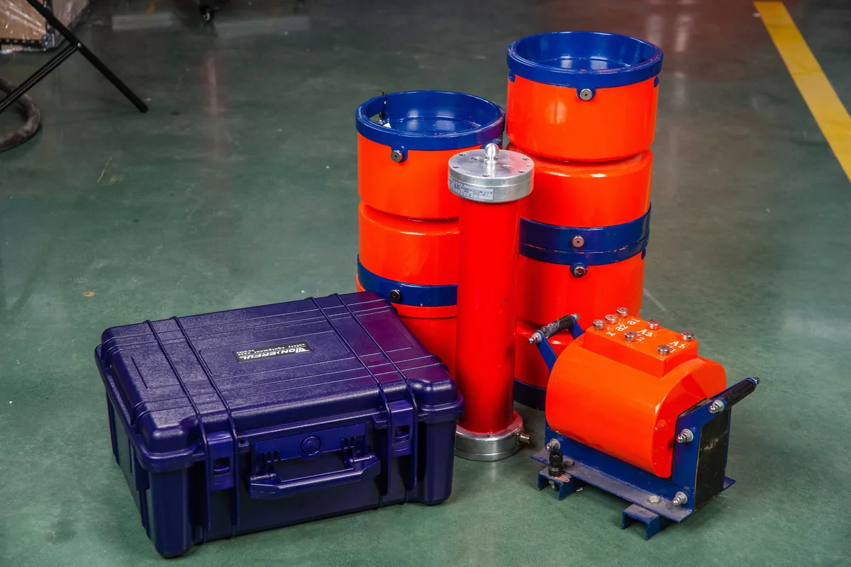
Variable-Frequency Series Resonant Test System
Compact variable-frequency series resonant test system for AC withstand testing. Displays test data and status on a green screen with real-time operating prompts, and calculates the capacitance of the test object.
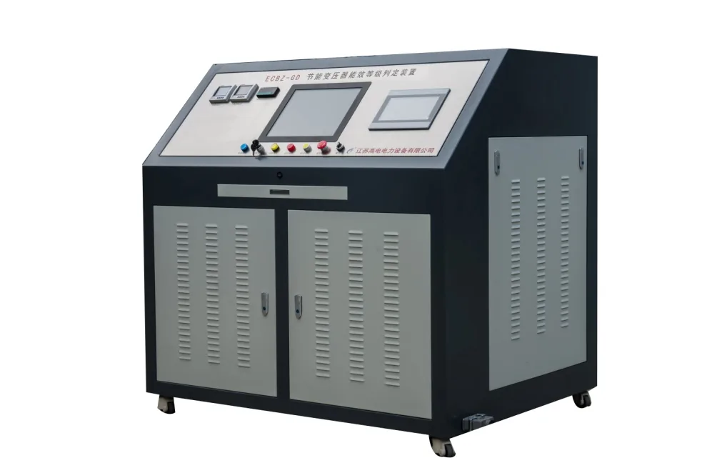
ECBZ-GD Energy-Efficient Transformer Energy-Grade Evaluation System
Automatic evaluation system for the energy-efficiency grade of distribution transformers up to 800 kVA at 10 kV/0.4 kV. Combines intelligent test sequence control, automatic wiring changeover, data processing, data upload and report generation in one bench.
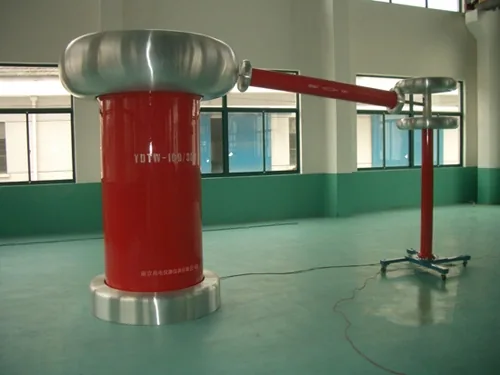
YDTW Partial-Discharge-Free AC Test Transformer
Partial-discharge-free power-frequency test transformer for verifying the insulation level of insulating materials, insulation structures and electrical products, and as a PD-free power-frequency test supply for transformers, capacitors, HV switchgear, instrument transformers and surge arresters.
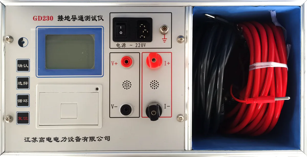
GD230 Ground Continuity Tester
Portable instrument for measuring the continuity resistance between the grounding down conductors of individual items of equipment in a substation. Controlled by a high-performance MCU with automatic current selection, on-board data retention and a thermal printer.
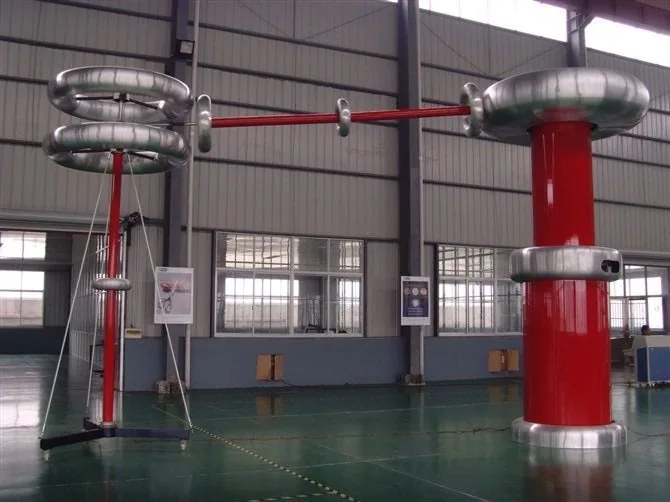
Automatic AC Withstand Voltage Test Set
GDNY-III automatic power-frequency withstand voltage test set, designed to the latest national industry test standards, for insulation strength tests on electrical products, components and insulating materials.
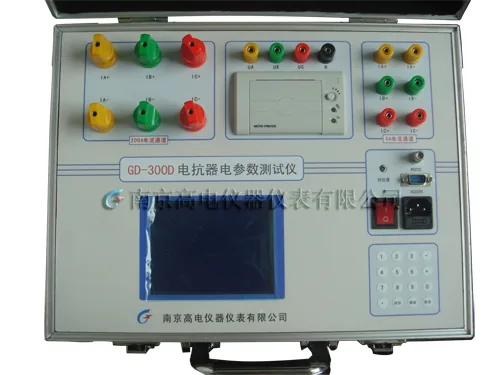
GD-300D Reactor Electrical Parameter Tester (Portable)
Portable instrument dedicated to measuring the electrical parameters of single-phase and three-phase reactors, including AC phase voltage RMS, average voltage, current RMS, active power, reactance and inductance, at 0.5 class accuracy.
More in High Voltage Test Equipment
Need the datasheet for this model?
Send us this product name plus your test requirements. We reply with specifications, photos and a formal quotation.