
Test Center Facilities
EMC Shielded Room for PD Testing
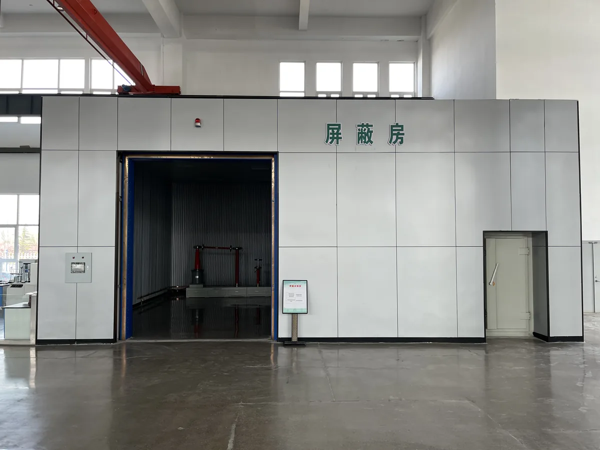
Modular bolted shielded enclosure built from 2 mm galvanised steel module plates with conductive gasketing, honeycomb waveguide ventilation, filtered power, dedicated grounding below 0.5 Ω and a double-glazed shielded observation window. Shielding effectiveness is 60 dB or better from 0.5 MHz to 1.6 MHz.
Overview
Modular bolted shielded enclosure built from 2 mm galvanised steel module plates with conductive gasketing, honeycomb waveguide ventilation, filtered power, dedicated grounding below 0.5 Ω and a double-glazed shielded observation window. Shielding effectiveness is 60 dB or better from 0.5 MHz to 1.6 MHz.
Standards & Compliance
Cited in this product’s specification
Benchmark standards for this equipment category
Systems in this category are commonly specified against these standards, linked to the issuing body. Final configuration and acceptance criteria follow the standard and edition you nominate.
- IEC 61010 — Safety requirements for electrical measuring equipment
- IEC 60060-2 — High-voltage test techniques - Measuring systems
- IEC 60270 — Partial discharge measurements
- GB/T 16927.1 — High-voltage test techniques
Application Scenarios
Request Specifications & Quotation
Tell us your test object ratings, the test items you need and the applicable standards. Our sales engineers reply with a configuration proposal and a formal quotation within 24 hours.
Get a QuoteDetailed Description
Foundation pit: before construction the foundation pit has to be excavated, with embedded pipes and grounding electrodes installed during the build. After construction the pit is backfilled and the floor surface treated, with the surface required to sit 200 mm below the test hall floor.
Structure and process: the shielded room is installed on the negative floor level inside the production workshop, with no slope at the threshold so that product trolleys can pass in and out easily. The shielding shell of the assembled shelter is made from 2 mm high-quality galvanised steel plate pressed and formed into unit module plates. The adjacent contact faces of the unit module plates are punched with a regular pattern of mounting holes; during assembly an elastic and anti-galvanic-corrosion conductive gasket is inserted and M8 galvanised bolts with waisted washers are tightened to fix the plates. The interior wall is filled with 50 mm sound-absorbing cotton plus a 0.6 mm perforated aluzinc corrugated acoustic panel for sound absorption. The inner layer of the shielding shell plate carries a section-steel support keel to increase rigidity and seismic resistance, and to guarantee flatness of the shielding body the support keel and unit modules are levelled, ground and cleaned of welding slag and grease. Openings are reserved for waveguide vents, filters and any other cables or equipment that have to pass through the shield, and after the process is complete the outer layer of every shielding module plate is painted, with the finish colour to the customer requirement, generally white-grey.
Ventilation: the system uses dedicated ventilation waveguide windows whose insertion loss corresponds to the shielding room specification. The window is a waveguide bundle of small waveguides with a hexagonal cross-section; for the same insertion loss a hexagonal waveguide gives a larger channel area than a square waveguide, increasing the ventilation area and reducing air exchange resistance. Air in and out is handled by an air exchanger through cut-off waveguide windows, with an opening reserved in the shielding shell, the window welded to the shell, a flanged decorative frame made to suit the exchanger, and an aluminium alloy louvre at the indoor outlet. Waveguide window sizes are customised.
Power filter: power for indoor lighting, socket outlets and similar has to pass through a filter before being supplied indoors. All indoor cables are run in galvanised steel conduit, and socket outlets are positioned as specified. Electrical fittings are executed to the process requirements; where there is no requirement, GB2887—90 applies.
Grounding: all electrical equipment in the system, including auxiliary equipment, must have its enclosure grounded, because a damaged insulation layer on an equipment supply cable or accidental contact can make the enclosure live and easily cause injury to people and damage to equipment. The shielded room uses a separate grounding system with a grounding resistance of less than 0.5 Ω; the ground lead is brought out from an underground grounding electrode, and the copper rod and bare copper wire are bolted together with copper lugs. A grounding copper bar of 40 x 3 mm cross-section and approximately 20 m in length is laid out indoors.
Interior finish: interior finish materials must be flame-retardant and waterproof (weak-alkali and oil resistant, waterproof and flame retardant), and the floor is poured concrete by the civil works contractor. Walls use 0.6 mm aluzinc steel sheet with micro-perforations for decoration and sound absorption. The ceiling uses 600 x 600 mm square micro-perforated aluminium tiles for decoration and sound absorption. Where the user has a requirement or specification, finish materials are selected to the user requirement provided the specification rules are not violated.
Electrical installation and observation window: the shielded room is fitted with switches and socket outlets, with the luminaire switches, outlets, quantities and positions arranged sensibly. Twelve 40 W incandescent luminaires are used to ensure the required test illuminance. A distribution and control cubicle is built to act as the main power control for the room, containing air switches and similar devices, to guarantee the electrical safety of all equipment. A double-glazed shielded vision window with a shielding wire mesh sandwiched between the panes is installed on the side of the console facing the test area. The wires are arranged vertically and tensioned straight, kept equidistant during installation for a good appearance and clear view. Both ends of the copper wire are welded securely to the angle steel in the window frame, and the frame has a reliable electrical connection to the grounding system.
Technical Specifications
| Shielding effectiveness | 0.5 MHz – 1.6 MHz, 60 dB or better |
|---|---|
| Grounding resistance | Less than 0.5 Ω (installed by the civil works contractor) |
| Shielding shell plate | 2 mm high-quality galvanised steel sheet, pressed into unit module plates |
| Module fastening | M8 galvanised bolts with waisted washers; elastic anti-galvanic-corrosion conductive gasket inserted at the joint |
| Internal wall infill | 50 mm sound-absorbing cotton plus 0.6 mm perforated aluzinc corrugated acoustic panel |
| Internal wall lining | 0.6 mm micro-perforated aluzinc steel sheet |
| Ceiling | 600 x 600 mm square micro-perforated aluminium tiles |
| Ventilation | Dedicated shielded waveguide windows, hexagonal cross-section, with an air exchanger and cut-off waveguide windows |
| Power filtering | Indoor lighting and socket power supplied through filters; cables run in galvanised steel conduit |
| Grounding bar | Copper bar, 40 x 3 mm cross-section, approximately 20 m long |
| Lighting | 12 off 40 W incandescent luminaires |
| Floor | Poured concrete (civil works) |
| Foundation pit surface | 200 mm below the test hall floor level |
| Electrical standard | GB2887—90 where no process requirement is specified |
Frequently Asked Questions
How is the shielded enclosure built?
What civil works are needed before installation?
What shielding performance does the room achieve?
Further Reading
Method and selection guides that cover the tests this instrument performs.
Reviewed by the Application Engineering Team at Nanjing Gaodian Electric Power Equipment
Specifications are taken from the manufacturer’s technical documentation. Final configuration and acceptance criteria follow the standard and edition you nominate — tell us your test list and we will confirm the ratings.
Related Products
Artificial Rain Test Room
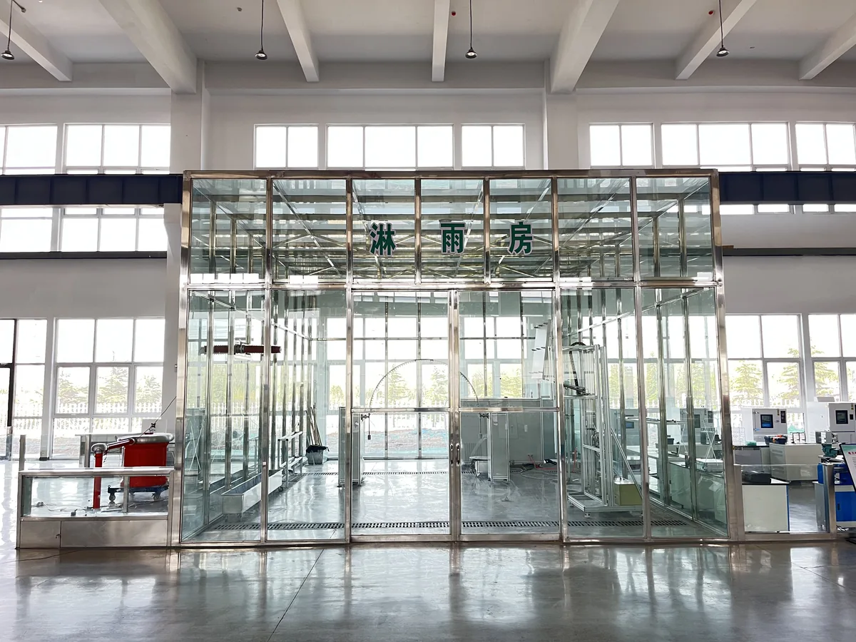
Construction specification for an artificial rain test zone, covering clear height, waterproofing of the roof and walls, seepage drainage with a ring drainage channel, mains water supply and 6 m³/h drainage, plus an anti-static control room with suspended ceiling, lighting and air conditioning.
ECBZ-GD Energy-Efficient Transformer Energy-Grade Evaluation System
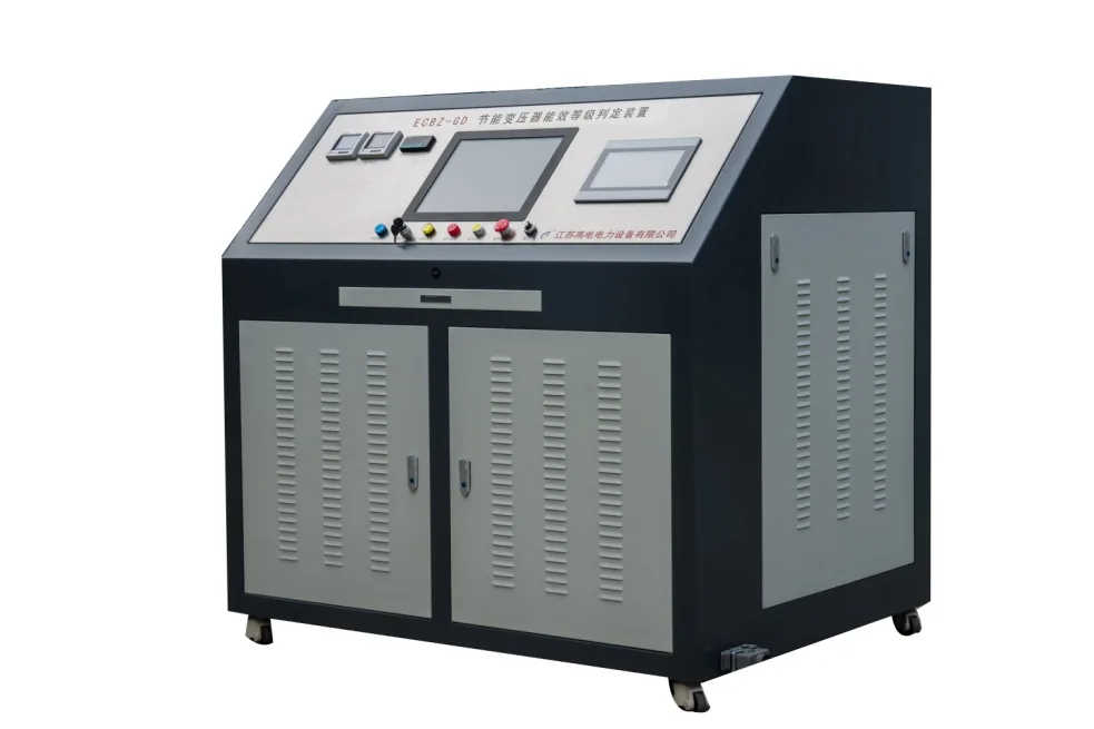
Automatic evaluation system for the energy-efficiency grade of distribution transformers up to 800 kVA at 10 kV/0.4 kV. Combines intelligent test sequence control, automatic wiring changeover, data processing, data upload and report generation in one bench.
HV Test Center Central Control Room
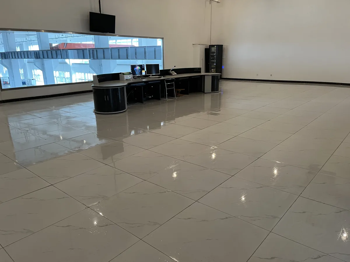
Build specification for the central control room and machine room of a high-voltage test centre. Covers clear height, anti-static raised flooring with a minimum 100 mm void, reserved cable penetrations, glass curtain wall and air conditioning to a constant 20 ±5 ℃.
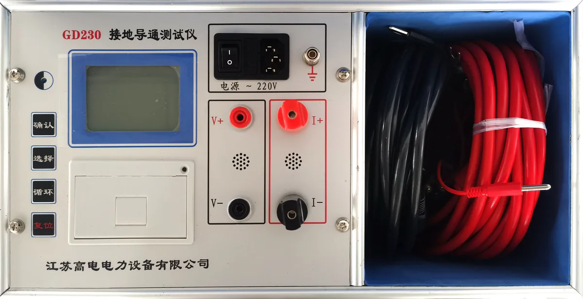
GD230 Ground Continuity Tester
Portable instrument for measuring the continuity resistance between the grounding down conductors of individual items of equipment in a substation. Controlled by a high-performance MCU with automatic current selection, on-board data retention and a thermal printer.
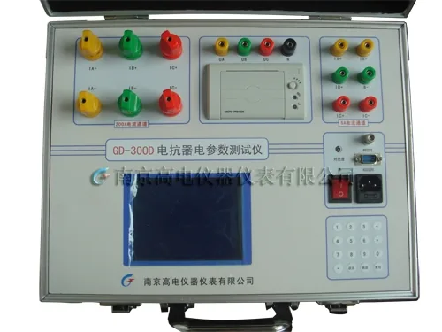
GD-300D Reactor Electrical Parameter Tester (Portable)
Portable instrument dedicated to measuring the electrical parameters of single-phase and three-phase reactors, including AC phase voltage RMS, average voltage, current RMS, active power, reactance and inductance, at 0.5 class accuracy.
GD-300D Reactor Electrical Parameter Tester (Built-in)
Panel-mounted version of the GD-300D reactor electrical parameter tester, using a 320 x 240 dot-matrix LCD with multi-screen menu operation and direct measurement of three-phase reactance, inductance and total active power.
More in Test Center Facilities
Need the datasheet for this model?
Send us this product name plus your test requirements. We reply with specifications, photos and a formal quotation.