A current transformer and a voltage transformer are both instrument transformers, but they are stressed differently and they fail in different ways. A CT reproduces a primary current on its secondary at a defined ratio, and its usefulness to protection collapses the moment its core saturates. A PT reproduces a primary voltage, and its accuracy depends mainly on how much burden the secondary circuit places on it. That difference is why the two test programs share parameters but not priorities — and why one test set does not automatically cover both.
This guide sets out what a CT test actually covers, what a PT test covers, and where the two overlap enough to share an instrument. It is written for utility protection and metering groups, transformer factories that also repair instrument transformers, and third-party laboratories that have to keep a mixed population of cores and windings in service.
What a CT test covers
A CT test program is built around one question: where does the core stop behaving linearly? Ratio and polarity testing confirms that the secondary current is proportional to the primary current and in the same direction, which is the minimum needed for relay settings to mean anything. On its own, though, a ratio check says little about behaviour during a fault, because it is normally performed at a small fraction of rated current. The excitation test — usually reported as knee point voltage and excitation current — establishes the onset of saturation and is the single most important measurement on a protection core. Winding resistance separates a genuine core or winding problem from a loose terminal or an undersized secondary cable, and the burden test measures the volt-ampere load the CT actually sees in service, because an accuracy class is only guaranteed up to the rated burden. For a current transformer, the methods for ratio, polarity, excitation and winding resistance are published in IEC 61869-2, which superseded IEC 60044-1; IEEE C57.13 is the equivalent reference in North American practice.
- •Ratio and ratio error — confirms the nameplate ratio and the error at the test point.
- •Polarity — a reversed secondary connection mis-operates differential, directional and distance protection.
- •Excitation and knee point (Vk / Ik) — defines where the core saturates and how much fault current the CT can transform within class.
- •Winding resistance — detects shorted turns, poor joints and secondary cable runs that were never accounted for.
- •Burden — the connected VA and power factor, checked against the rated burden on the nameplate.
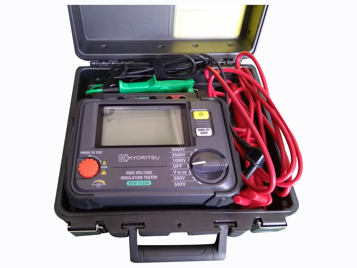
- •Insulation resistance — a pre-test check between primary, secondary and earth, run before the measurement set.
What a PT test covers
A voltage transformer needs the same confidence in ratio and polarity, but the parameters that dominate are different. Because a PT sits in parallel with the system, its ratio and error are usually verified at low voltage rather than at rated primary voltage, and the error is read together with the burden the unit will actually carry — relays, meters and transducers whose combined VA can push the winding out of its accuracy class. The excitation (no-load) test shows the no-load current and where the core begins to saturate, which matters on a PT that has to stay accurate during a system disturbance. Winding resistance is measured on both the primary and the secondary, and on a grounded or cascade design the test is normally performed on the electromagnetic unit. The dielectric side — power-frequency withstand, and impulse where specified — is where a PT is stressed hardest, and the applicable levels and methods come from IEC 61869-3 and IEC 61869-1, which superseded IEC 60044-2.
- •Ratio and ratio error — measured at the specified test voltage and burden.
- •Polarity and phase displacement — including the connection group on three-phase units.
- •Winding resistance — primary and secondary, checked against design values.
- •Excitation / no-load current — shows the onset of core saturation.
- •Burden — the real connected load, which is what limits accuracy in service.
- •Dielectric and insulation checks — power-frequency withstand and insulation resistance, set by the rated voltage of the unit.
CT and PT test items side by side
| Test item | Current transformer (CT) | Voltage transformer (PT / VT) | Why the test is run |
|---|---|---|---|
| Ratio and error | Low-voltage or primary-injection ratio, error at rated and over-current points | Low-voltage ratio and error at the specified burden | Nameplate ratio must match protection and metering settings |
| Polarity | Absolute polarity of the secondary winding | Polarity and phase displacement, including connection group | Reversed polarity mis-operates differential, directional and distance schemes |
| Excitation / knee point | Knee point voltage Vk and excitation current — the dominant test | No-load current and saturation onset, at or near rated voltage | Defines protection performance on a CT and disturbance behaviour on a PT |
| Winding resistance | Secondary winding resistance, and primary where accessible | Primary and secondary winding resistance | Separates a real winding fault from a bad joint or a long lead |
| Burden | Secondary VA and power factor seen in service | Secondary VA including connected relays and meters | Accuracy class is only guaranteed up to the rated burden |
| Insulation | Primary-to-secondary and secondary-to-earth insulation resistance | Insulation resistance plus power-frequency withstand on the unit | Safety, and pre-energisation acceptance before commissioning |
Combined CT/PT tester or dedicated turns-ratio tester?
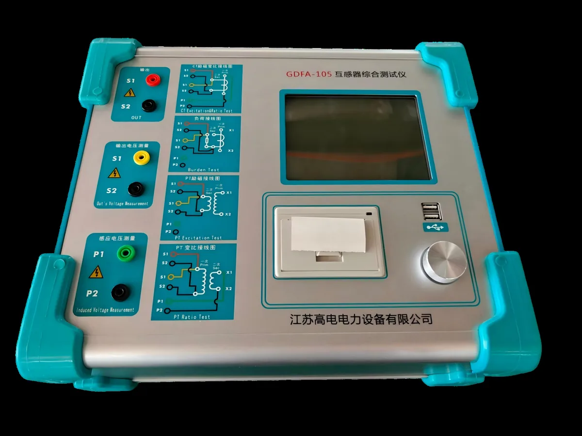
Where a combined CT/PT test set fits
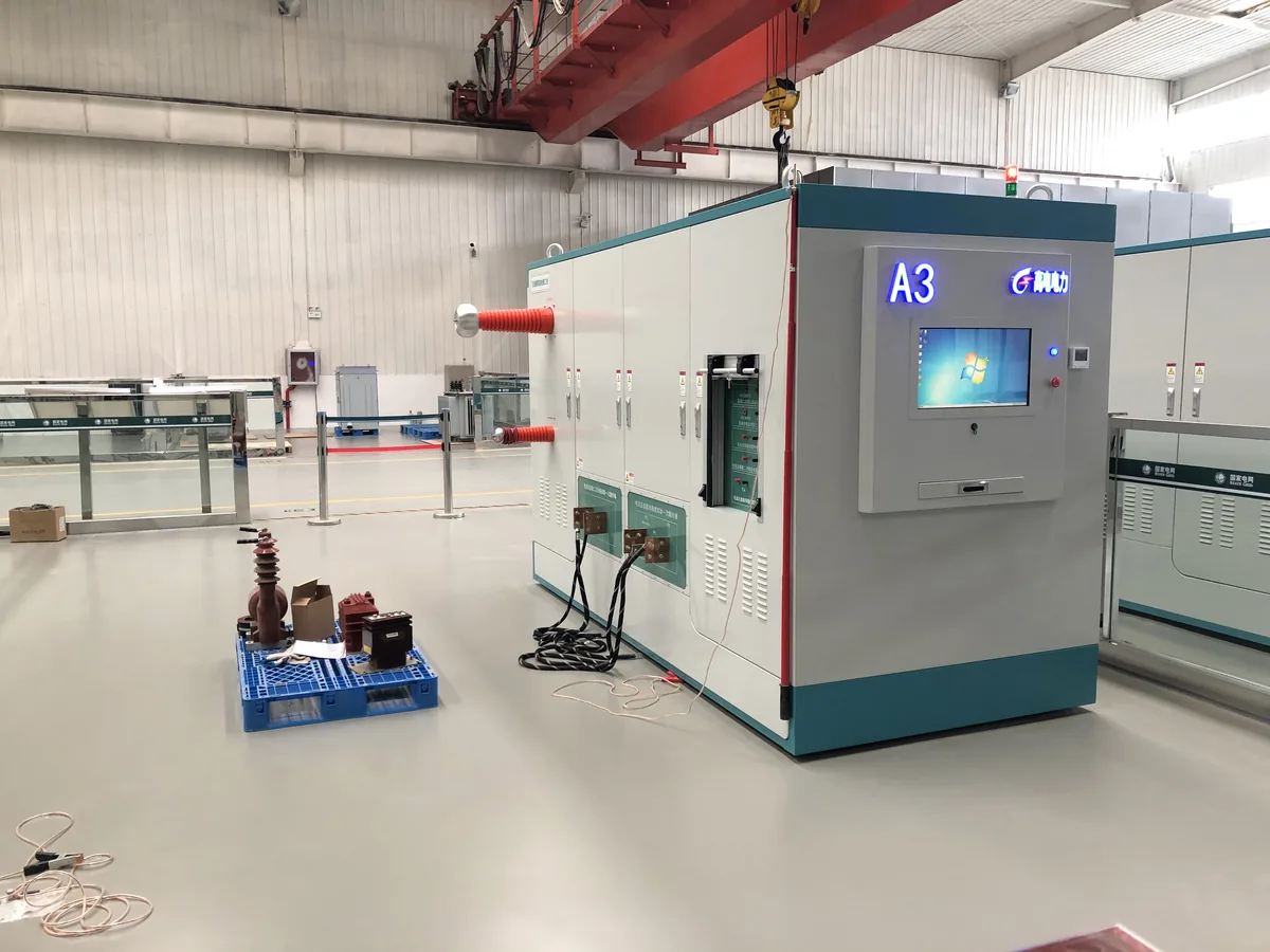
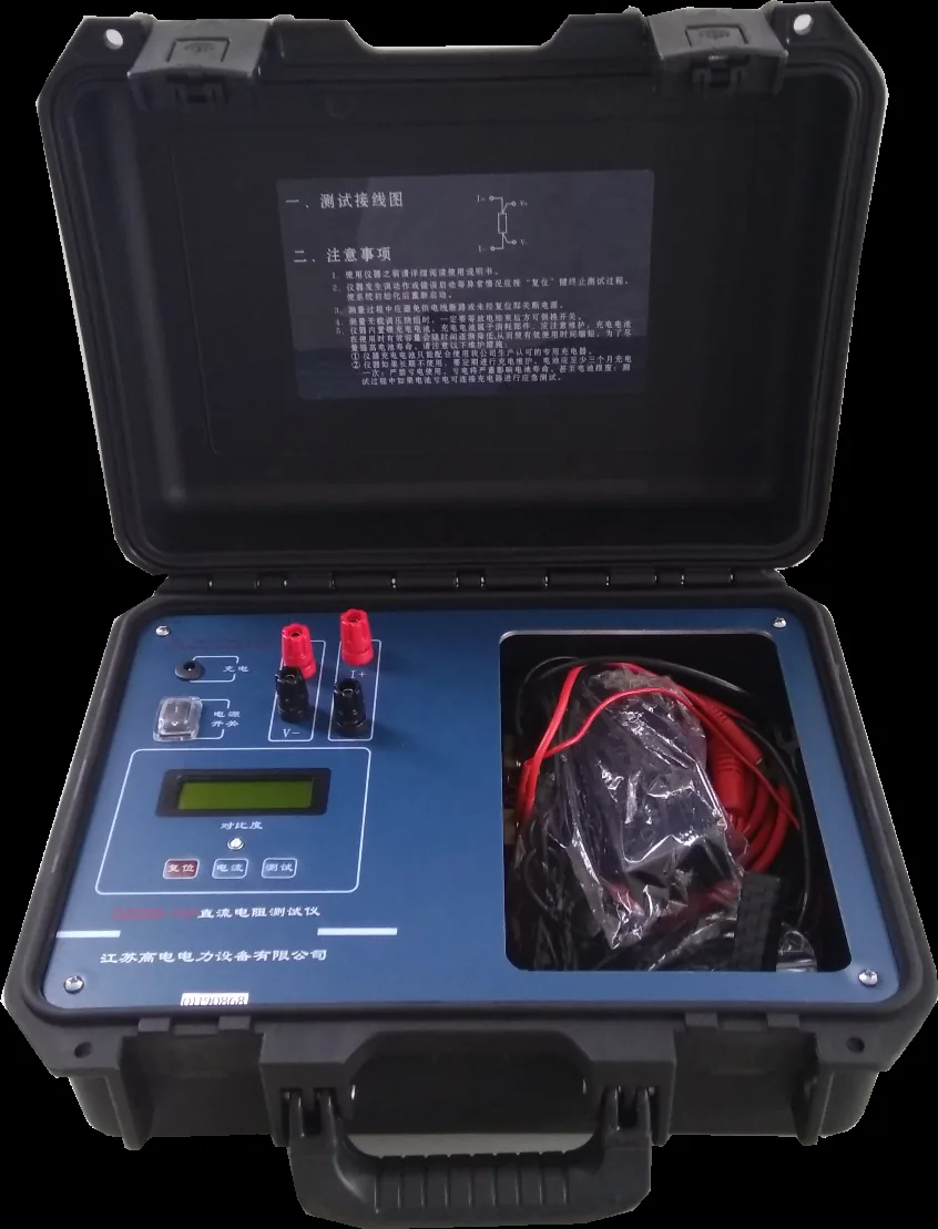
If your schedule mixes CTs and PTs — the normal situation for a utility test group, a repair workshop or a third-party laboratory — a combined CT/PT comprehensive tester removes the need for two separate excitation sources and two separate measurement chains. One set covers ratio, polarity, excitation, winding resistance and burden on both families: you select the test type, connect once, and the same unit produces the record. The practical gain is not the box count but the changeover time. On a mixed batch, every re-cabling between a CT test and a PT test is a chance to mis-wire, which is precisely the error the polarity test exists to catch. Combined sets are usually specified with an excitation output able to reach the knee point of the largest protection CT in the population, and with a metering-grade channel for ratio and error. Field and factory use pull in different directions here: for substation work the priorities are weight, portability and tolerance of an unstable site supply, while in a factory or laboratory the same instrument normally sits on a bench with fixed wiring, where automation and data export count for more than the case.
Where a dedicated turns-ratio tester is enough
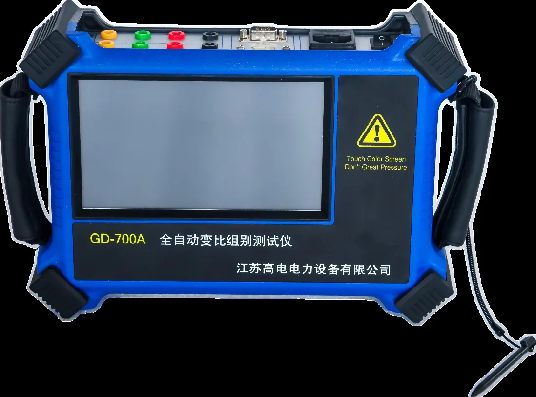
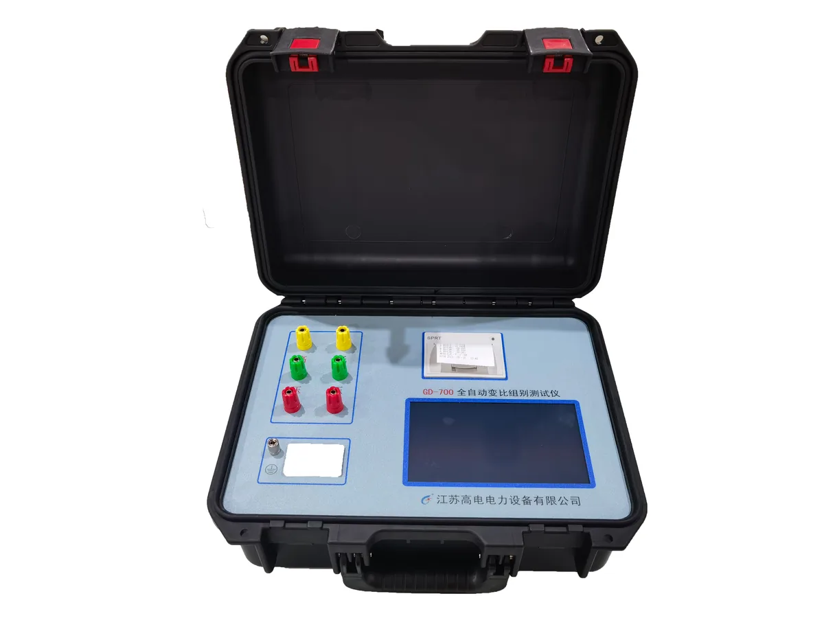
If the acceptance criterion is ratio and polarity only, a dedicated turns-ratio tester such as the GD700A or GD-700 does the job with a shorter setup and a simpler operator interface, and it is the usual choice where throughput matters — incoming inspection of a large population, or a production step that requires one ratio record per unit. A ratio instrument cannot, by definition, produce a knee point voltage or a burden measurement, so it becomes the wrong tool the moment the test sheet asks for excitation data on a protection core or for the burden on a PT that feeds a heavy metering panel. Many works solve this by keeping a ratio tester at the bench and a comprehensive set in the laboratory, rather than choosing between the two.
Sizing the tester to your CT and PT population
- •Knee point voltage first. The tester must drive the highest Vk on your list with enough compliance to reach it, not merely approach it. A population containing protection cores sets that ceiling.
- •Rated primary current range. Confirm the unit covers your smallest and largest ratio steps without an external booster, because the extremes of the range are where most set-ups run out of capability.
- •Accuracy class and error measurement. If you report metering-class errors, the measuring channel has to be suitable for that duty; where the test set itself is verified, the applicable national metrology regulation applies — JJG 169 in China.
- •Burden range and power factor. The burden test has to cover the VA range you actually see, at the power factors your relays and meters present.
- •Secondary taps and winding configuration. Multi-tap CTs and multi-ratio PTs need a routine that steps through taps without manual re-wiring.
- •Field or factory. A portable unit trades automation for weight and supply tolerance; a bench unit trades portability for throughput and data handling.
If you take one point from this guide, take this one: size the instrument to the worst case in your population, not the average. Find the protection CT with the highest knee point voltage and the PT with the heaviest secondary burden, confirm the candidate tester reaches both with margin, then decide whether your CT and PT workloads are large enough to justify one dual-purpose set or whether a ratio-only instrument plus a shared excitation source covers the year. A population list with rated currents, accuracy classes, knee point voltages and burdens is enough to map a configuration against.
Reviewed by the Application Engineering Team at Gaodian Electric Power Co., Ltd
Gaodian Electric Power Co., Ltd designs and manufactures high-voltage test systems for transformer factories, power utilities and third-party laboratories. This guide is a selection reference, not a compliance statement: final equipment configuration and acceptance criteria follow the standard and edition you nominate.